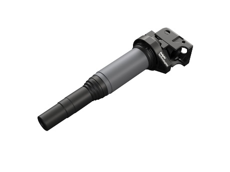
Ignition Coils

Optimum wire length
More wire generates differences in voltage, and in turn extra pressure, that can cause the breakdown of insulation and wire coatings. So, we tightly control the length of wire between adjacent primary and secondary windings. The result? Our secondary winding is thinner and much longer than the primary in order to get the output needed for the voltage to jump the spark plug gap.
Smart processes
Ignition coil windings should also be evenly distributed and neatly wrapped. That’s why we wind both primary and secondary coils as smoothly and tightly as possible, directly onto a proprietary steel core. This approach helps to ensure maximum magnetic power in every turn of the wire. We also wind our secondary coils into more bays than many of our competitors for more consistent voltage distribution and reliable coil performance.
High quality components
We only ever use high-quality wires, and coating that resists the cracks, pin holes and imperfections that might cause other ignition coils to fail. A special Epoxy helps insulate these wires and keeps them separated. Gaps in the epoxy can reduce the integrity of the insulation, so we also employ a special vacuum technique to remove air bubbles and imperfections, and help prevent internal arching and shorts.
The Delphi Difference
-
100 years of OE experience, supplier to the world’s top automakers
-
OE heritage and knowledge built into every aftermarket part
-
Comprehensive portfolio for a wide range of vehicles and model years
-
Streamlined SKUs for easy inventory management
-
Support through tools, tips and training

Related product resources and downloads

Resource Highlights
In this article, you will find out how to diagnose a defective ignition.
Important info on the ignition coil service
If the vehicle fails to start up, you can hear the engine misfiring or the car accelerates noticeably worse than normal, the ignition coil may be defective. The same applies if the engine warning light illuminates, the engine control unit switches to emergency operating mode or an error code is displayed.
Like many other components, the ignition coil is also subject to a certain degree of wear and tear. Its service life is generally between 60,000 and 80,000 kilometers – but a number of factors may lead to a lower service life.
Incorrect voltage supply
If the ignition cables are damaged or the battery output drops, insufficient voltage is supplied, increasing the time required to charge the ignition coil. In turn, this may damage the ignition module, which could eventually lead to a defect in the ignition coil.
Temperature problems
In particular in the case of pencil coils, the coils are subject to extreme heat. This may also shorten the service life of an ignition coil.
Vibrations
Primarily with pencil coils, as a result of increased vibrations in the cylinder head, the coil may break.
Accuracy of fit of ignition cables and spark plug connectors
The same applies to spark plugs: they have to match the corresponding connections on the ignition coil (DIN is not SAE or M4). If an incorrect connection is used, the contacts burn away.
The correct tools
Ultimately, technically correct tools that meet the manufacturer’s specifications are to be used at all times. This applies in particular where special tools are available. There is therefore a risk of pencil coils installed directly in the spark plug bore tilting and breaking unless tools are used to ensure straight removal. Last but not least, any fastening screws of the ignition coil are always tightened to the correct torque.
Step by Step
Step 1
Diagnosis
Visual inspection
Before the ignition coil inspection, the ignition system should therefore undergo a visual inspection.
- Is there mechanical damage or cracking?
- Are the electrical cables and plugs undamaged and free from corrosion and kinks?
- Is there enough power supply from the battery?
- Is the valve cover gasket intact?
Where external damage causes cannot be ruled out in this way, one available option is to measure the resistance with an ohmmeter.
Step 2
Diagnosis
Measuring the resistance with an ohmmeter
Conventional ignition coils for transistor ignition systems and electronic ignition systems with an electronic map ignition can be tested when installed, using the electrical resistance in the primary and secondary area.
Step A: Preliminary examination
- Battery voltage at least 11.5 Volts?
- Engine speed sensor functioning?
- Hall sensor intact?
- Fuse on the engine control unit OK?
Step B: Test the power supply
- Remove the primary plug from the coil
- Turn on the ignition
- The voltage between clamp 1 (negative pole) and 15 (positive pole) should be at least 11.5 Volts
Step C: Measure secondary resistance
- Use the ohmmeter to measure the secondary resistance on the outlet of the coil
- UTarget values: Target values should be in the kΩ range (at 20°C)
Get in touch

Find out where to buy Delphi parts


