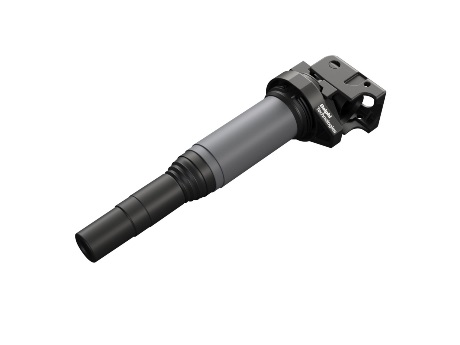
Ignition Coils

Optimum wire length
More wire generates differences in voltage, and in turn extra pressure, that can cause the breakdown of insulation and wire coatings. So, we tightly control the length of wire between adjacent primary and secondary windings. The result? Our secondary winding is thinner and much longer than the primary in order to get the output needed for the voltage to jump the spark plug gap.
Smart processes
Ignition coil windings should also be evenly distributed and neatly wrapped. That’s why we wind both primary and secondary coils as smoothly and tightly as possible, directly onto a proprietary steel core. This approach helps to ensure maximum magnetic power in every turn of the wire. We also wind our secondary coils into more bays than many of our competitors for more consistent voltage distribution and reliable coil performance.
High quality components
We only ever use high-quality wires, and coating that resists the cracks, pin holes and imperfections that might cause other ignition coils to fail. A special Epoxy helps insulate these wires and keeps them separated. Gaps in the epoxy can reduce the integrity of the insulation, so we also employ a special vacuum technique to remove air bubbles and imperfections, and help prevent internal arching and shorts.
The Delphi Difference
-
100 years of OE experience, supplier to the world’s top automakers
-
OE heritage and knowledge built into every aftermarket part
-
Comprehensive portfolio for a wide range of vehicles and model years
-
Streamlined SKUs for easy inventory management
-
Support through tools, tips and training

Related product resources and downloads

Resource Highlights
In this article, you find out about the ignition coils design and mode of operation.
Structure of ignition coil
Ignition coils work on the transformer principle. They basically consist of a primary winding, a secondary winding, the iron core and a housing with isolation material, nowadays two-component epoxy resin. On the iron core of individual thin steel sheets two coil elements are applied e.g.:
- The primary winding is made of thick copper wire with approx. 200 windings (diameter approx. 0.75 mm2)
- The secondary winding is made of thin copper wire with approx. 20,000 windings (diameter approx. 0.063 mm2)
As soon as the primary coil circuit closes, a magnetic field is generated in the coil. Induced voltage is generated in the coil by self induction. At the time of ignition, the coil current is switched off by the ignition output stage. The instantaneously collapsing magnetic field generates a high induction voltage in the primary winding. This is transformed on the secondary side of the coil and converted in the ratio of "number of secondary windings to primary windings". A high voltage flashover occurs at the spark plug, which in turn leads to ionization of the sparking distance and thus to a flow of current.
This continues until the saved energy has been discharged. As it jumps, the spark in turn ignites the fuel / air mixture.
The maximum voltage depends on:
- The ratio of the number of windings from the secondary winding to primary winding
- The quality of the iron core
- The magnetic field
Get in touch

Find out where to buy Delphi parts


