Resource Highlights
In this article you will find out about the MAF sensor:
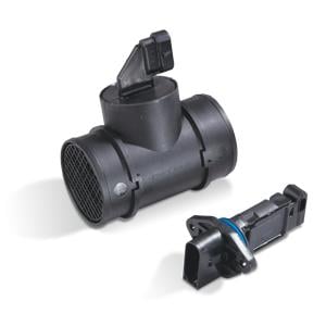
Full name Mass Air Flow Sensor, it’s more commonly known as a MAF sensor, air meter or sometimes simply MAF. While it might have many names, it’s responsible for just one, but still very important job: measuring the amount of air entering the engine. The ECU or PCM then uses this information to calculate the correct amount of fuel needed for an optimal air-fuel ratio. Of course, without this information the ECU will not be able to accurately control fuel injection, resulting in an engine that will either idle roughly or worse case, not at all. Since a number of other parts i.e. faulty spark plugs, wires, injectors, etc, may mirror these symptoms, MAF sensor failure can be difficult to diagnose. However, with some expert advice from OE manufacture Delphi, you’ll know what causes it, what to look out for, and crucially, how to replace it when it fails.
How does a MAF sensor work?
Installed in the intake pipe between the air filter housing and the intake manifold, most MAF sensors work on the hot wire principle. Put simply, a MAF has two sensing wires. One is heated by an electrical current, the other is not. As air flows across the heated wire, it cools down. When the temperature difference between the two sensing wires changes, the MAF sensor automatically increases or decreases the current to the heated wire to compensate. The current is then changed to a frequency or a voltage that is sent to the ECU and interpreted as air flow. The quantity of air entering the engine is adjusted accordingly.
Why do MAF sensors fail?
Since the MAF sensor is responsible for measuring air flow into the engine, they have a lot of air passing through them. In fact, more than 9000 liters of air can flow through the engine for every liter of fuel used. That’s a lot of air! And with that comes the potential for a lot of contamination. Dust, dirt and other debris can all get into the sensor and are one of the primary causes of MAF failure.
Such contamination could occur as early as 18,000-25,000 miles, depending on the vehicle model. On small or compact cars, for example, the MAF sensor can clog quicker, as it is situated in a smaller engine bay subjected to more risk in critical areas (oil vapor flows and combustion debris). In this case, a replacement becomes the equivalent of a long drain oil service… it almost becomes a service-style repair.
Other common failure problems include:
- A contact fault at the electrical connections
- Damaged measuring elements
- Mechanical damage from vibrations or an accident
- Measuring element drift (exceeding the measuring framework)
What to look out for in a failing MAF sensor?
When a MAF sensor fails, the engine will not know the right amount of fuel to add, causing several common signs:
- Check engine light: as with most engine management components, a problem with the MAF sensor often causes the check engine light to come on.
- Engine runs rich at idle or lean under load: this would typically point towards a contaminated hot wire.
- Engine runs rich or lean: caused by the MAF continuously misreporting airflow into the engine – a diagnostic procedure will be required to confirm this.
- Rough idle or stalls: a failed MAF sensor will not send any airflow information to the ECU preventing it from accurately controlling fuel.
- Excessive vibrations when stationary.
- RPMs changing noticeably without driver input.
Troubleshooting a MAF sensor
To identify the source of any MAF sensor faults, consider the following steps:
- Conduct an electronic test of the MAF sensor and read any fault codes using a diagnostic tool.
- Check the connector for a correct fit and good contact.
- Check the MAF sensor and measuring elements for damage.
- Check the voltage supply with the ignition switched on (circuit diagram for pin assignment is necessary). Ref. value: 7.5-14 V.
- Check the output voltage or frequency with the engine running (circuit diagram for pin assignment is necessary). Ref. value: 0.5V resp. 0 – 12.000 Hz.
- Check the connection cables between the removed control unit connector and sensor connector for transmission (circuit diagram for pain assignment necessary). Ref. value: approx. 0 ohm.
Common fault codes
Common fault codes and causes include:
- P0100: MAF circuit malfunction
- P0101: MAF circuit range/performance
- P0102: MAF circuit low input
- P0103: MAF circuit high input
- P0104: MAF circuit intermittent
- P0171 system too lean (bank 1) and P0174 system too lean (bank 2) are also often caused by a faulty or contaminated MAF sensor.
How to replace a faulty MAF sensor?
Once you’ve identified that the MAF sensor may be at fault, it’s best practice to follow these simple steps:
- To begin, connect a diagnostic tool to your vehicle. Select the correct make, model, year, and engine code of the vehicle you’re working on. Record the fault codes, and check the live data parameters for the MAF sensor. Then exit the diagnostic software and switch off the ignition.
- You’ll also need to check the feeds, ground, and wiring. Connect the oscilloscope. Ideally, a break out lead should be used to prevent puncturing the wiring's insulation and causing a future wiring issue. To get a reading, snap the throttle open and observe the pattern.
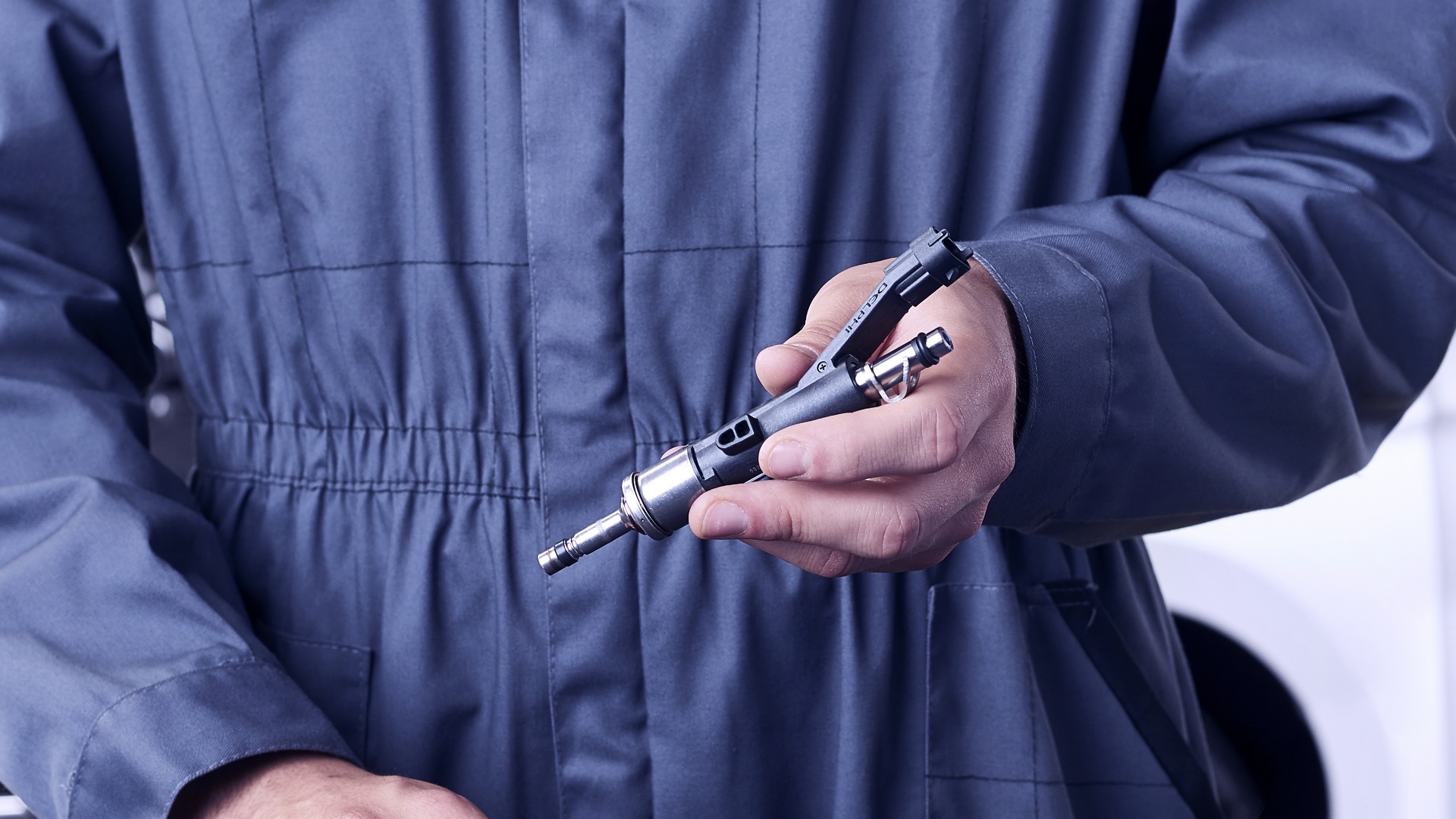
- Once it’s determined that the MAF sensor is at fault, you’ll need to replace it. Remove the connector and then the fastening screws. Next, remove the sensor from its housing.
- Inspect the flow tube to ensure there are no cracks in the plastic housing. If there are, you will need to replace the entire unit – not just the probe. If the flow tube is crack-free, then you’re ok to replace the sensor probe only.
- Remember it’s important to handle the sensor connector only. Never touch the electronics as this may damage the sensor probe.
- Carefully slide the new sensor probe into the flow tube, then tighten the fasteners and replace the connector.
- Reconnect the diagnostic kit and delete any fault code(s). Run the engine, and recheck for any new fault codes. Exit the diagnostic software and switch off the ignition. Finally, check that the check engine light has been extinguished, then carry out a road test.
Contact Us
Visit our Contact hub to find a range of enquiry types suited to help you find the exact support you are looking for.