- Product Information
- Product Resources
- Enquire
- Related Products
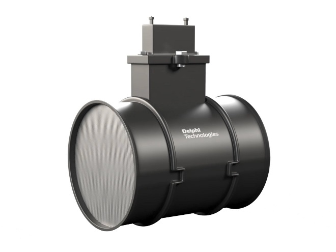
Innovative OE design
We build our OE expertise into every MAF sensor we make. Featuring a proprietary temperature compensation design, they offer outstanding performance over a wide range of ambient temperatures. And are fast to respond to changing engine conditions – typically less than 15 milliseconds to respond to 90 percent of a flow change. Innovative, dual-heated elements on specific references also help to ensure optimal performance, fuel efficiency, and reduced emissions

OE engineered and tested
By testing and calibrating to OE specifications, our MAF sensors provide the same accurate readings and airflow output as the OE. Each sensor is tested on state-of-the-art sonic nozzle-testing equipment capturing over 6,000 data points per flow, for optimal calibration accuracy. They’re also flow tested to match the OE for signal stability (noise), temperature compensation (the ability of the MAF sensor to measure airflow accurately from -30°C to 70°C) and electromagnetic compatibility.

Never remanufactured MAF sensor
Some things are better new. That’s why every sensor we make – whether with or without the housing—is built with all-new components and never remanufactured. Remanufactured MAFs are simply cleaned and tested, so any contamination on the sensor may not be eliminated, resulting in inaccurate readings to the ECU.
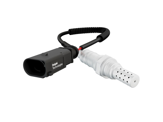
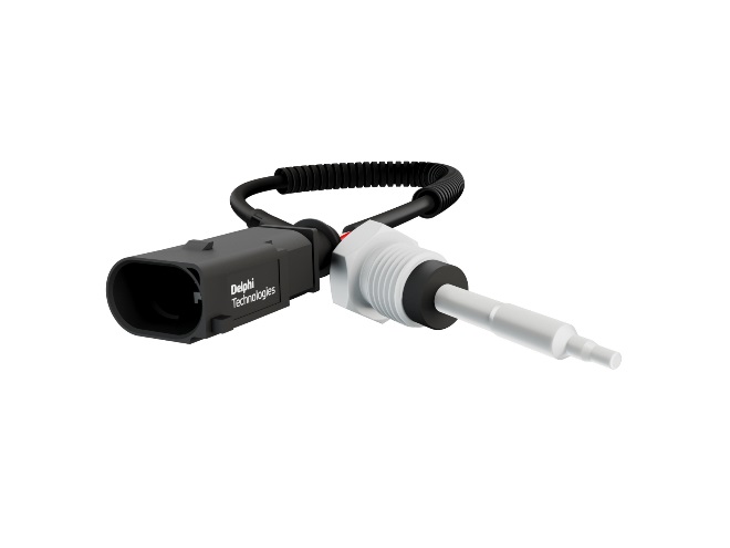
Greener probe-only technology
It’s often the electronics on the sensor probe that fail, meaning it’s not always necessary to replace the complete part. So we developed a probe-only solution, in addition to a full range of complete units. By eliminating the plastic housing, this provides a greener, more cost-effective and faster repair option.

The complete package
With Delphi you get access to the complete package: the range, advanced DS diagnostics including the ability to look at live data, both at idle and max RPM, to determine if the MAF sensor is reporting the correct data, expert training and support and vehicle technical information including wiring diagrams, component locations and guided diagnostic procedures.
The Delphi Difference
-
100 years of OE experience, supplier to the world’s top automakers
-
OE heritage and knowledge built into every aftermarket part
-
Comprehensive portfolio for a wide range of vehicles and model years
-
Streamlined SKUs for easy inventory management
-
Support through tools, tips and training

Related product resources and downloads

Resource Highlights
When should I test a crank position sensor?
There are numerous things to indicate that you might have an issue with your crank sensor. Firstly, the warning engine light might be illuminated on your dashboard. Has your engine been stalling? When you’re sat idling, does the engine sound rough? Is the engine not delivering the power you’re used to, and is your fuel efficiency not as good as it once was? Does your engine crank but not start? If you experience any of these, it’s worth testing.
Are there different crank sensors?
There are two main types of sensors – an inductive sensor, and a Hall effect sensor. The general rule is that an inductive sensor has two wires, and a Hall effect has three. However, some two-pin inductive sensors have an extra wire for shielding so please check carefully before carrying out any test.
What equipment do I need to test a crank position sensor?
In our video we carry out the tests using the Delphi VTI platform, a multimeter and an oscilloscope.
Get in touch
Find out where to buy Delphi parts