Resource Highlights
In this article you will find out about the MAP sensors:
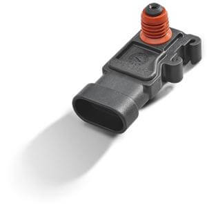
Typically found in fuel injected engines, the manifold absolute pressure (MAP) sensor is one of the sensors an engine control module (ECM) uses to calculate fuel injection for optimal air-fuel ratio by continuously monitoring intake manifold pressure information. More commonly a mass airflow (MAF) sensor is used in place of a MAP sensor, however, turbocharged engines will typically use both a MAP and a MAF sensor. The MAP sensor also provides a vital role in helping the ECM determine when the ignition should occur under varying engine load conditions.
Whichever sensor your engine uses, the ECM will not be able to optimize fuel injection without accurate air mass information from a working sensor. And poor air-fuel ratio at the very least will cause performance issues and premature engine wear. A MAP sensor failure can be difficult to diagnose, but with the help from Delphi, we can explain what causes it, what to look out for, and how to replace it if it fails.
How does a MAP sensor work?
The MAP sensor is typically located on the intake manifold, either next to or on the throttle body itself. (On a forced-induction engine, the MAP sensor can be found on the intake tract before the turbo.) Inside the MAP sensor is a sealed chamber that either has a vacuum or a controlled pressure that is calibrated for the engine. Dividing the sensor vacuum and the vacuum from the intake manifold is a flexible silicon wafer (a.k.a. ‘chip’) with a current running through it.
The MAP sensor performs ‘double duty’ as a barometric pressure sensor as soon as the key is turned on. With the key turned on (prior to the engine starting) there is no vacuum in the engine applied to the MAP sensor therefore it’s signal to the ECM becomes a baro reading helpful in determining air density. When you start the engine, pressure in the intake manifold decreases creating a vacuum that is applied to the MAP sensor. When you press on the gas accelerator pedal, the pressure in the intake manifold increases, resulting in less vacuum. The differences in pressure will flex the chip upward into the sealed chamber, causing a resistance change to the voltage, which in turn tells the ECU to inject more fuel into the engine. When the accelerator pedal is released, the pressure in the intake manifold decreases, flexing the clip back to its idle state.
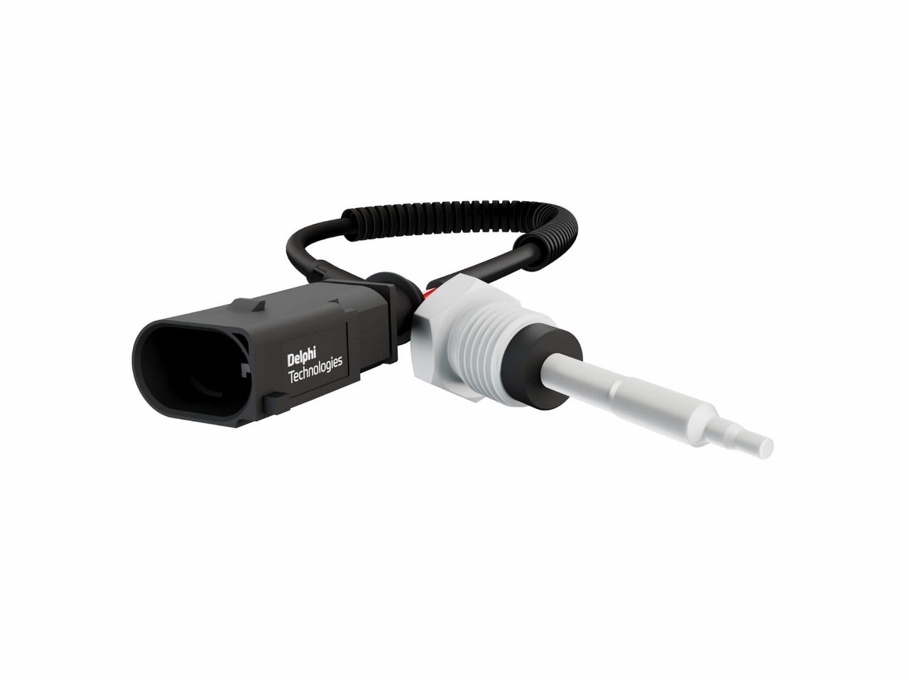
The ECU combines the manifold pressure readings from the MAP sensor with data coming from the IAT (intake air temperature), ECT (Engine Coolant Temperature) sensor, baro reading and engine speed (RPM) to calculate air density and accurately determine the engine's air mass flow rate for optimal air-fuel ratio.
Why do MAP sensors fail?
Like most electric sensors, MAP sensors are sensitive to contamination. If the map sensor uses a hose, the hose can become clogged or leak and unable to read pressure changes. In some cases, extreme vibrations from driving can loosen its connections and cause external damage. Electrical connectors can also melt or crack from overheating due to close proximity to the engine. In either of these scenarios, the MAP sensor will need to be replaced.
What to look out for in a failing MAP sensor
A faulty MAP sensor will affect an engine's air-fuel ratio. If the ratio is incorrect, ignition inside the engine will occur at an improper time in the combustion cycle. If severe pre-detonation continues over an extended time, the internal parts of the engine (such as pistons, rods, rod bearings) will become damaged and eventually lead to catastrophic failure. Look for these warning signs:
- Rich air-fuel ratio: Look for rough idle, poor fuel economy, slow acceleration and a strong smell of gasoline (especially at idle)
- Lean air-fuel ratio: Look for surging, stalling, lack of power, hesitation on acceleration, backfiring through the intake, and overheating
- Detonation and misfire
- Failed emissions test
- Check engine light
A rebuilt engine is much more of a hassle than replacing a sensor, so if your engine is experiencing any of the symptoms above, consider troubleshooting your MAP sensor.
Common MAP sensor fault codes
Here is a list of codes that are associated with the MAP sensor to look for if your check engine light has turned on:
- P0068: MAP/MAF - Throttle Position Correlation
- P0069: Manifold Absolute Pressure - Barometric Pressure Correlation
- P0105: MAP Circuit Malfunction
- P0106: MAP/Barometric Pressure Circuit Range/Performance Problem
- P0107: Manifold Absolute Pressure/Barometric Pressure Circuit Low Input
- P0108: MAP Pressure Circuit High Input
- P0109: MAP / Baro Pressure Circuit Intermittent
- P1106: MAP/BARO Pressure Circuit Range/Performance Problem
- P1107: Barometric Pressure Sensor Circuit Low Voltage
Note: Sometimes different sensors or other faulty parts can cause these codes to set. Even if your engine is experiencing the symptoms listed above and is firing one or more of the OBD-II codes listed, it is recommended to test the MAP sensor to confirm it is faulty.
How to troubleshoot a MAP sensor
Before any tests, inspect the physical appearance of the MAP sensor. Begin by checking the connector and wiring for any damage, such as melted or cracked wires, and confirm there are no loose connections. Disconnect the sensor and inspect the pins; they should be straight and clean with no signs of corrosion or bending. Next, inspect the hose (if applicable) connecting the sensor to the intake manifold for any signs of damage and that it has a tight connection to the sensor. Lastly, take a look inside the hose to make sure it is free of contamination.
If everything passes physical inspection, you can test the MAP sensor using a digital multimeter set to 20V and a vacuum pump.
- With the battery on and engine off, connect the multimeter ground to the negative battery terminal and run a quick plausibility by checking the voltage of the battery. It should be around 12.6 volts.
- Consult the manufacturer’s service manual to identify the signal, ground, and 5-volt reference and back-probe the wires.
- Turn the ignition switch on without starting the engine. The multimeter should (typically) display a voltage between 4.5 to 5 volts for the 5-volt reference, a steady 0 volts for the ground wire, and between 0.5 and 1.5 volts for the signal wire on non turbo applications and between 2.0 and 3.0 for turbo applications. Consult OEM factory service information for the exact specs on your vehicle.
- Start the engine with the signal wire back-probed. The multimeter should display a voltage between .5 to 1.5 volts at sea level on non turbo charged vehicles and 2.0 to 2.5 volts on turbocharged models.
- Turn the engine off but keep the ignition on.
- Under the hood, disconnect the MAP sensor from the intake only.
- Connect a hand vacuum pump and note the current voltage from the signal wire.
- Increase the vacuum on the sensor using the vacuum pump.
- The voltage should steadily drop as the vacuum increases.
If your voltage differs greatly on either test or the voltage change is erratic, the MAP sensor is faulty and will need to be replaced.
How to replace a faulty MAP sensor
Replacing a bad MAP sensor varies by vehicle, so please consult the manufacturer’s service manual for instructions for any specific instructions. Once the faulty sensor has been removed, it’s a straight forward installation for the new part.
- Locate the MAP sensor on the intake manifold, either next to or on the throttle body itself, or on the intake manifold.
- Remove any screws or bolts holding the sensor in place.
- Disconnect the electrical connector. Note: Do not force removal as the connector may contain a locking tab that may need to be removed prior to unlatching the connector from the sensor.
- If applicable, detach the vacuum hose from the sensor. Note: It is recommended to replace the vacuum hose with a new hose when replacing the sensor.
- Compare the new and old sensors.
- If applicable, reconnect the vacuum hose.
- Reconnect the sensor electrical connector.
- Reinstall any screws or bolts that hold the sensor in place.
- Double-check all connections to make sure everything is secured.
Note: Depending on the vehicle and if a trouble code was set, a diagnostic tool may be required to reset the check engine light.
Related article resources and products


Contact Us
Visit our Contact hub to find a range of enquiry types suited to help you find the exact support you are looking for.