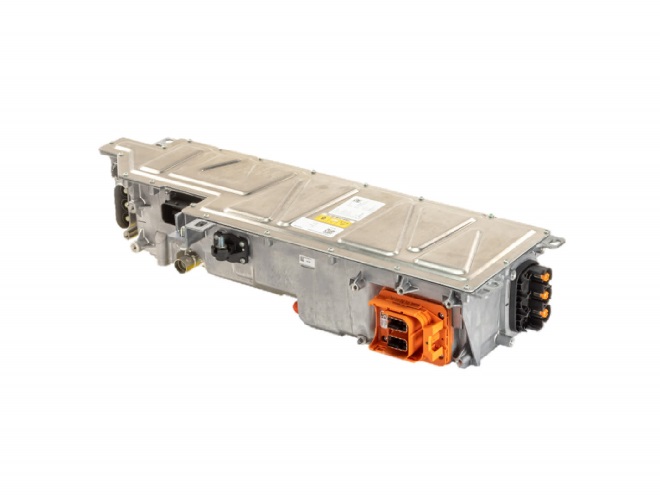
- Product Information
- Product Resources
- Enquire
- Related Products
OE Part Number | Applications | DT Part Number |
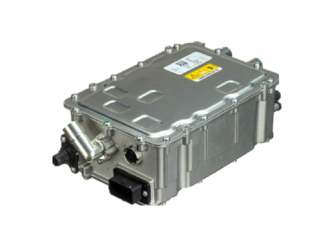
12368487431 | BMW 225XE (F45) , X1 (F49), M5 Sedan (F60) | PFV10000-12B1 |
What is the difference between an inverter and DC/DC converter in an electric vehicle?
Much like how internal combustion engines and alternators work together on conventional vehicles, hybrid cars and electric motors use inverters and converters to manage power to and from the battery pack to the motors and other on-board systems.
Inverters transform direct current (DC) from the battery into alternating current (AC) to power the vehicle. Inverters also control the motor and convert it to a generator, transferring braking energy back into the battery.
Converters control the DC voltage from the battery, either stepping it up or down based on the system and the power needed. DC/DC converters usually step down the high voltage from the battery pack to the 12-volts used by radios, headlights, and more.
An OE solution for aftermarket power electronics
Inverters and converters work together to manage the vehicle's electric drive and accessory systems. However, many of today’s inverters and converters can be complex, expensive, and prone to failure from excessive heat. They are also heavy and take up a lot of room on the vehicle, compromising both trunk and passenger compartment space. Delphi OE solution combines the inverter and DC/DC converter into one unit.
Delphi CIDD is cost-effective and saves vital weight and space in hybrids (HEV), plug-in hybrid electric (PHEV), and electric vehicles (EV). And by leveraging patented OE technology - Viper-enabled inverter’s double-sided cooling - it tackles the issue of overheating, allowing higher power outputs from a smaller package and increased range.
Combined Inverter and DC/DC Converter (CIDD)
- Enhances durability and reliability through features designed to withstand under the hood and environmental factors such as debris and temperature extremes.
- Improves voltage distribution functionality, enabling both low-side and high-side power for everything from headlights to power steering and air conditioning systems.
- Provides maximum packaging flexibility and space savings by moving the DC/DC unit from its standard location in the rear to the front of the vehicle.
- Enables better power range and minimizing power losses through the elimination of cabling, cooling hoses, connections, and housings, all while simplifying maintenance and repair.
To learn more about OE quality aftermarket EV parts you can trust, contact your Delphi representative today.
The Delphi Difference
-
100 years of OE experience, supplier to the world’s top automakers
-
OE heritage and knowledge built into every aftermarket part
-
Comprehensive portfolio for a wide range of vehicles and model years
-
Streamlined SKUs for easy inventory management
-
Support through tools, tips and training

Related product resources and downloads
Resource Highlights
In this article you will find out about the oxygen sensors:
The oxygen sensor, otherwise known as the O2 sensor, does what its name suggests – it measures the amount of oxygen in the exhaust. Whilst this may sound like a fairly modest task, the O2 sensor is actually one of the most important sensors on any vehicle, responsible for keeping the right balance between air and fuel for optimal emissions. Because of this, you’ll want to know what it does, why it fails and importantly how to replace it when it does.
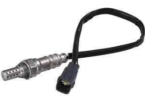
How does an oxygen sensor work?
Most cars have at least two oxygen sensors located throughout the exhaust system; at least one in front of the catalytic converter and one or more downstream from the catalytic converter. The “pre-cat sensor” regulates fuel supply, while the downstream sensor measures the efficiency of the catalytic converter.
O2 sensors can typically be categorised as either a narrow band or wide band sensor. A sensing element sits inside the sensor, encased in a steel housing. Oxygen molecules from the exhaust gas pass through tiny slots or holes in the sensor’s steel shell to reach the sensing element, or nernst cell. On the other side of the nernst cell, oxygen from the air outside the exhaust travels down the O2 sensor and makes contact. The difference in the amount of oxygen between that present in the outside air, and that present in the exhaust promotes the flow of oxygen ions and produces voltage.
If the exhaust gas mixture is too rich and there is too little oxygen in the exhaust, a signal is sent to the engine’s Electronic Control Unit (ECU) to decrease the amount of fuel added into the cylinder. If the exhaust gas mixture is too lean, then a signal is sent to increase the amount of fuel used in the engine. Too much fuel produces hydrocarbons and carbon monoxide. Too little fuel produces nitrogen-oxide pollutants. The sensor signal helps keep the mixture just right. Wide band O2 sensors have an additional O2 pumping cell to regulate the amount of oxygen present in the sensing element. This allows measurement of a much wider air/fuel ratio.
Why do O2 sensors fail?
Since the oxygen sensor is in the exhaust stream, it can become contaminated. Common sources of contamination include an excessively rich fuel mixture condition or oil blow-by in an older engine and engine coolant being burnt in the combustion chamber as a result of an engine gasket leak. It is also exposed to extremely high temperatures, and like any component can wear over time. These can all affect the oxygen sensor’s response characteristics, resulting in an extended response time or a shift in the sensor voltage curve and in the long run reduced sensor performance.
What to look out for in a failing O2 sensor
When the oxygen sensor fails, the computer can no longer sense the air/fuel ratio, so it ends up guessing. For this reason, there are a few tell-tale signs to look out for:
- Check engine light: whilst the check engine light can come on for many reasons, it is normally down to an emission related issue.
- Poor fuel economy: a faulty oxygen sensor will upset the air to fuel mixture resulting in increased fuel usage.
- Rough engine idle or misfiring: since the oxygen sensor output help control engine timing, combustion intervals and air to fuel ration, a faulty sensor can cause the vehicle to run rough.
- Sluggish engine performance.
Troubleshooting an oxygen sensor
To identify the source of any O2 sensor faults, consider the following steps:
- Read any fault codes using a diagnostic tool. Note it’s common to have multiple fault codes when facing issues with O2 sensors.
- Lambda sensors have an internal heater, so check the resistance of the heater – it will usually be quite low.
- Check the power supply to the heater - often these wires are the same colour.
- Inspect the electrical connector for damage or dirt.
- Inspect the exhaust manifold and fuel injectors for leaks as well as the condition of the ignition components – these may affect sensor operation.
- Check the O2 sensor is reading correctly by confirming the O2 value with a four, or five gas emission analyser.
- Use an oscilloscope to check the signal at both idle and approx. 2,500 rpm engine speed.
- Use live data to check for signal if the sensor wiring is difficult to access.
- Check the condition of the probe element protective tube for signs of damage and contamination.
Common fault codes for O2 sensors
Common fault codes and causes include:
- P0135: oxygen sensor in front of the catalytic convertor 1, heating circuit / open
- P0175: system too rich (bank 2)
- P0713: fuel trim malfunction (bank 2)
- P0171: system too lean (bank 1)
- P0162: O2 sensor circuit malfunction (bank 2, sensor 3)
How to replace an O2 sensor
Before you replace the sensor, you need to diagnose the problem. Connect a diagnostic tool, such as Delphi’s DS, select the correct vehicle and read the fault code(s). Confirm the fault code by selecting live data and comparing the value of the suspect faulty sensor to that of a known working sensor. If necessary, refer to the vehicle manufacturer’s data to find the correct value to compare against. Other tooling or equipment may be required to determine if it is the actual sensor and not the wiring that is causing the problem.
- Because many late model vehicles have multiple oxygen sensors, be sure you correctly identify the bad sensor so you do not mistakenly replace the wrong one. Vehicle manufacturers identify “bank1” vs. “bank2” and “front / rear” vs. “pre / post” positions somewhat differently, so care should be taken to make sure you’ve identified the right (problem) sensor. The best way to do this is to look at real-time data using a diagnostic tool.
- Next unplug the wire connection.
- Then use a spanner – or dedicated O2 socket wrench - to unscrew the sensor from its seating. Once unscrewed, discard the old sensor and replace with the new unit.
- Most oxygen sensors come with a special electrically conductive anti-seize compound applied to the threads, so it’s merely a matter of threading the new sensor into the void left by the old one.
- To protect against the sensor becoming welded into its threading, Delphi sensors come with anti-seize compounds either pre-applied or included in the box. If required, apply the compounds to the new sensor before re-fitting. Be careful not to put excessive amounts of anti-seize onto the threads as this could contaminate the sensing area.
- Tighten the sensor to the recommended torque.
- Once the sensor is in place, plug in the electronic connector.
- Now reconnect the diagnostic tool and delete any related fault codes.
- Finally, run the ignition and confirm that the check engine light is extinguished, then perform a road test.

Visit our Technician Library for access to Documents and Downloads
Get in touch
Find out where to buy Delphi parts