
Resource Highlights
In this article, we’ll cover fault codes, but also show a clear path to follow in order to resolve the concern.
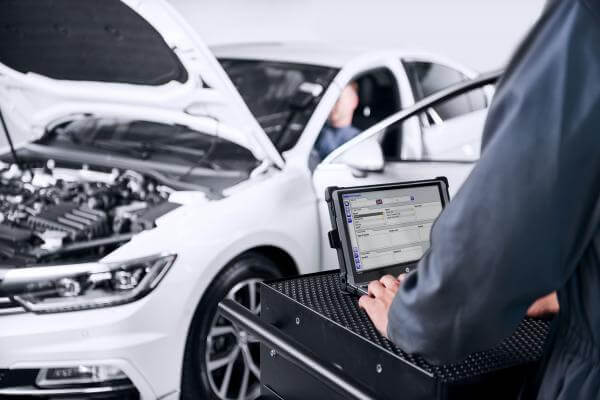
With diagnostics becoming more and more essential to a garage's business, it is important that the diagnostic procedure is as efficient as possible.
Many people use fault codes as the only diagnosis, and there is a lot to be learned from fault codes; however, more in-depth diagnosis is often necessary.
In this article, we’ll cover fault codes, but also show a clear path to follow in order to resolve the concern. One problem associated with fault codes and the messages with those codes is trying to interpret exactly what they mean.
Correctly interpreting diagnostic fault codes is critical to successful repairs.
Fault Codes
Fault codes are broken down into the following sections, each of which relates to a specific system or sub-system.
P = Powertrain.
B = Body.
C = Chassis.
U = Communication
For powertrain codes, the following applies:
P0XXX and P2XXX are generic (NOT manufacturer specific) codes.
P1XXX and P3XXX are manufacturer specific codes.
For body, chassis and communication codes, the following applies:
B0XXX and B3XXX are generic (NOT manufacturer specific) codes.
B1XXX and B2XXX are manufacturer specific codes.
The third digit indicates a sub menu (detailed below).
1 = Fuel and Air.
2 = Fuel and Air Metering.
3 = Ignition System or Misfire.
4 = Auxiliary Emission Control System.
5 = Vehicle Speed Control and Idle Control System.
6 = Computer Output Circuits.
7 = Transmission.
8 = Transmission.
From the above information, for example, we can see that a code of P0301 reads as a generic powertrain code showing an ignition system fault or misfire on cylinder number one.
Although this information is useful, further checks are necessary to determine the exact cause of the fault. It is also worth remembering that just because a warning lamp is not illuminated, it does not mean that a fault is not present. It is possible that the fault has happened for long enough to be logged by the ECU, or that the code is not recognized by the diagnostic tester.
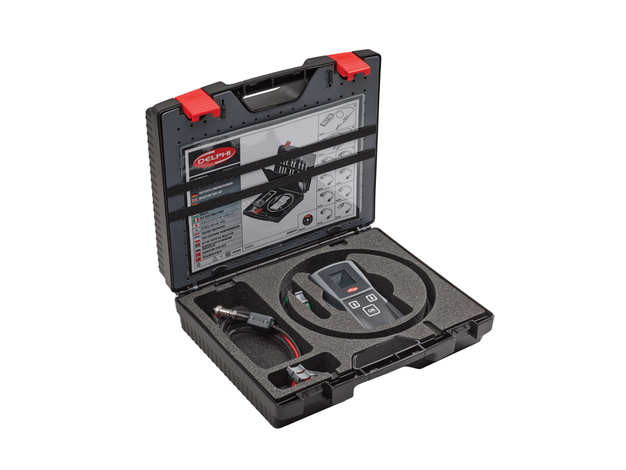
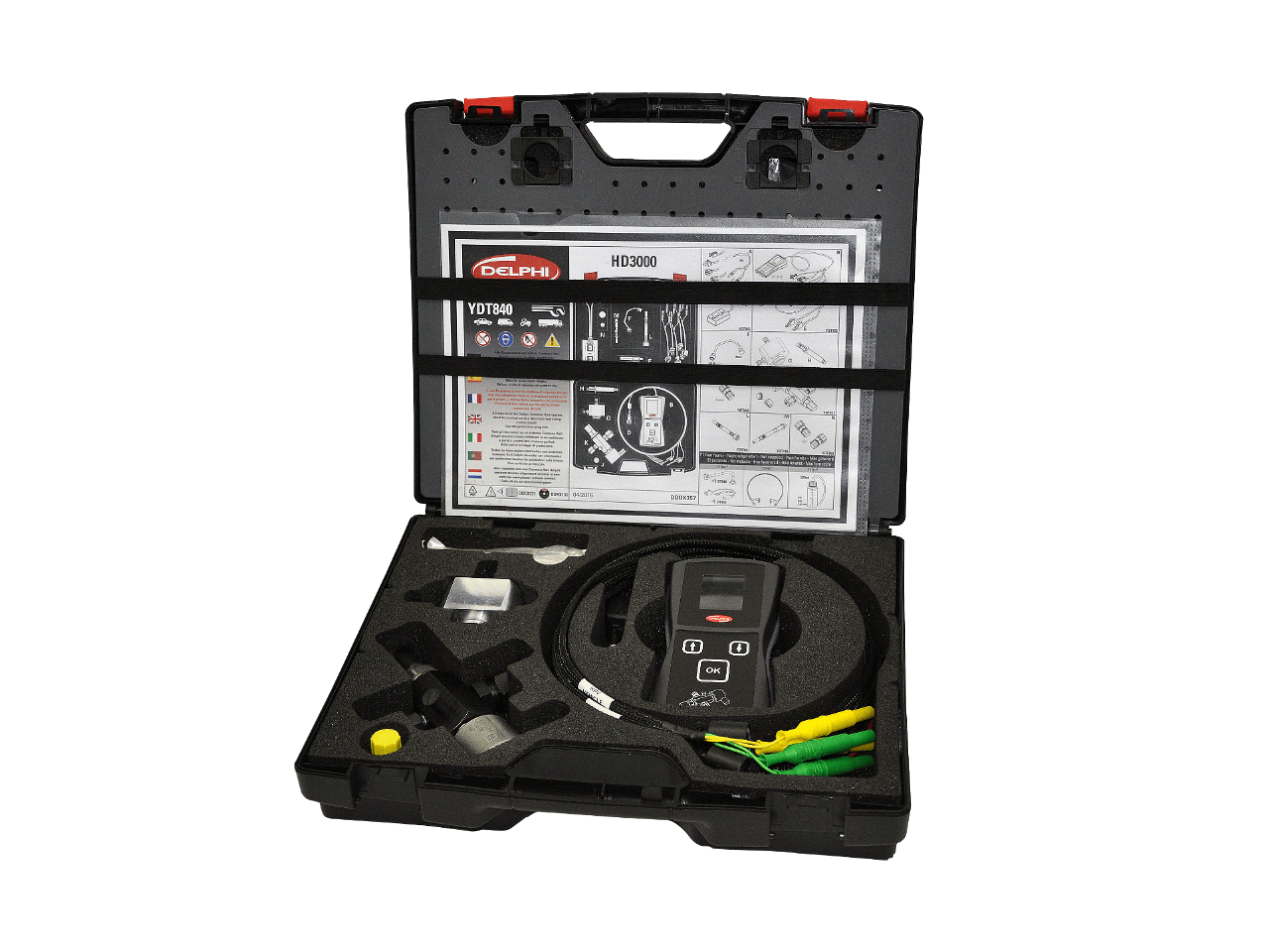
It is important to use all the equipment at your disposal, such as live data, exhaust gas analyzers, fuel pressure testers and oscilloscopes, to make your job as straightforward as possible.
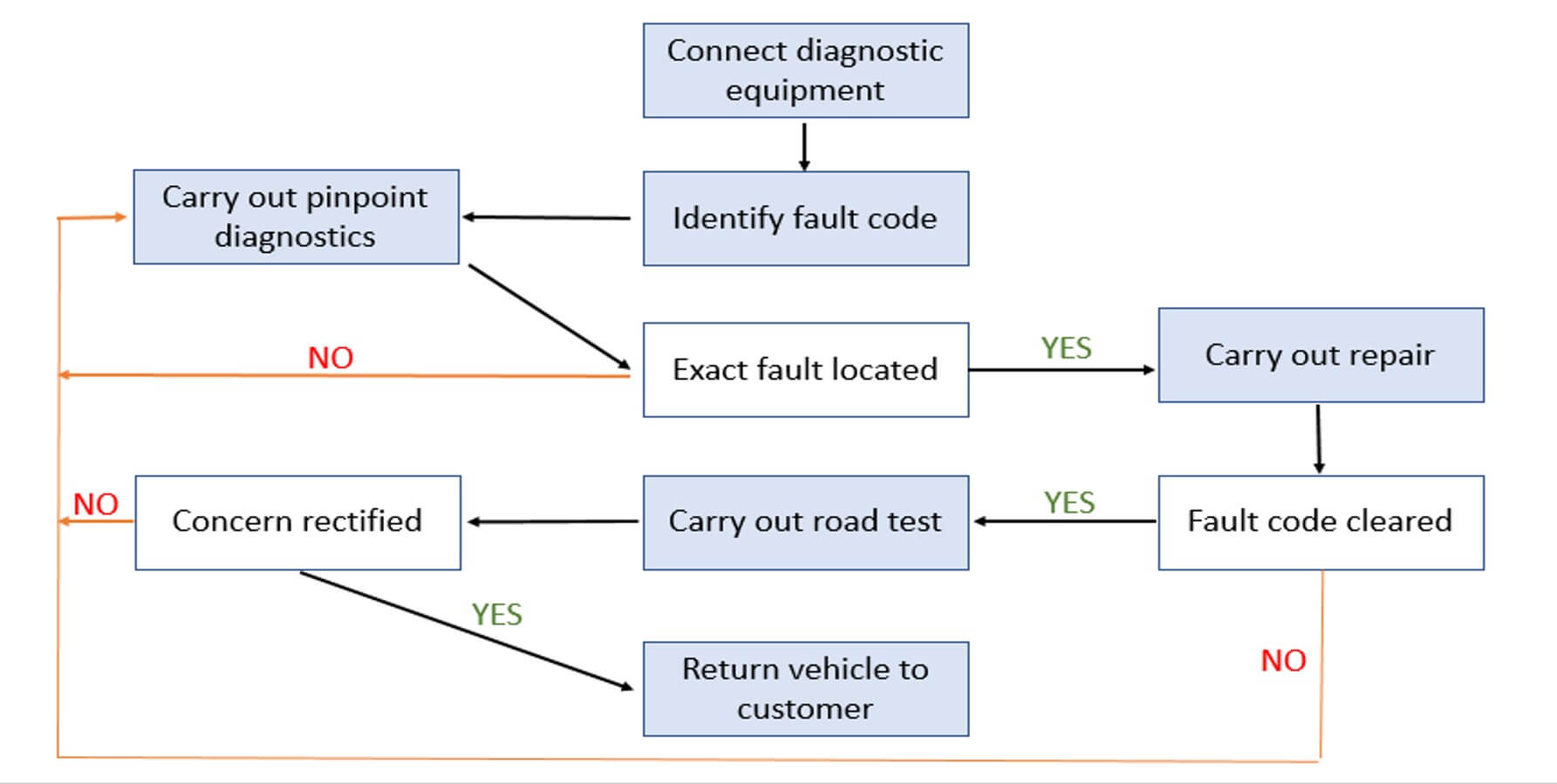
The flow chart below shows a logical approach to the use of fault codes and the additional diagnostics that may be required to efficiently diagnose faults.
Related article resources and products


Contact Us
Visit our Contact hub to find a range of enquiry types suited to help you find the exact support you are looking for.