
- Product Information
- Product Resources
- Enquire
- Related Products
Designed to provide safety and comfort while driving, Advanced Driver Assistance Systems (ADAS) are becoming increasingly common in latest generation vehicles. Visit our quick guide to learn more about the main systems available on the market today.
These vehicles can be equipped with over 10 different types of environment monitoring functions, utilizing different detection methods & sensors. These essential functions for both safety & comfort can need calibrating as a result of diagnostics, service, replacements, and repairs.

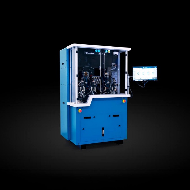
Empower safety with Delphi’ CRC-150 ADAS equipment

The universal modular equipment developed for the calibration of front sensor Advanced Driver Assistance Systems on multi-brand cars and commercial vehicles, designed to be used with the Delphi DS vehicle diagnostic tool.
Key features of the Delphi ADAS solution
Delphi’ multi-brand, modular ADAS equipment and DS diagnostic software with integrated OEM procedures delivers garages a cost effective, flexible and accurate route into ADAS servicing. Read on to learn more about the key features of the Delphi ADAS calibration equipment (CRC-150).

Coverage for the Delphi ADAS solution
Delphi’ ADAS solution includes dynamic and static variations for front radar and blind spot calibration, as well as camera calibration for front, rear, 360o overview, and night vision camera. Covering 31 vehicle brands, 146+ models with radar, and 284+ models with camera, our continuous improvement program means our coverage will expand with subsequent software developments.

The comprehensive ADAS calibration solution from Delphi

Learn more about ADAS calibration in our brand new how-to video series
ADAS camera calibration
ADAS Type 1
ADAS Type 3
The Delphi Difference
-
100 years of OE experience, supplier to the world’s top automakers
-
OE heritage and knowledge built into every aftermarket part
-
Comprehensive portfolio for a wide range of vehicles and model years
-
Streamlined SKUs for easy inventory management
-
Support through tools, tips and training

Related product resources and downloads

Resource Highlights
In this article, we’ll cover fault codes, but also show a clear path to follow in order to resolve the concern.
With diagnostics becoming more and more essential to a garage's business, it is important that the diagnostic procedure is as efficient as possible.
Many people use fault codes as the only diagnosis, and there is a lot to be learned from fault codes; however, more in-depth diagnosis is often necessary.
In this article, we’ll cover fault codes, but also show a clear path to follow in order to resolve the concern. One problem associated with fault codes and the messages with those codes is trying to interpret exactly what they mean.

Correctly interpreting diagnostic fault codes is critical to successful repairs.
Fault Codes
Fault codes are broken down into the following sections, each of which relates to a specific system or sub-system.
P = Powertrain.
B = Body.
C = Chassis.
U = Communication
For powertrain codes, the following applies:
P0XXX and P2XXX are generic (NOT manufacturer specific) codes.
P1XXX and P3XXX are manufacturer specific codes.
For body, chassis and communication codes, the following applies:
B0XXX and B3XXX are generic (NOT manufacturer specific) codes.
B1XXX and B2XXX are manufacturer specific codes.
The third digit indicates a sub menu (detailed below).
1 = Fuel and Air.
2 = Fuel and Air Metering.
3 = Ignition System or Misfire.
4 = Auxiliary Emission Control System.
5 = Vehicle Speed Control and Idle Control System.
6 = Computer Output Circuits.
7 = Transmission.
8 = Transmission.
From the above information, for example, we can see that a code of P0301 reads as a generic powertrain code showing an ignition system fault or misfire on cylinder number one.
Although this information is useful, further checks are necessary to determine the exact cause of the fault. It is also worth remembering that just because a warning lamp is not illuminated, it does not mean that a fault is not present. It is possible that the fault has happened for long enough to be logged by the ECU, or that the code is not recognized by the diagnostic tester.
It is important to use all the equipment at your disposal, such as live data, exhaust gas analyzers, fuel pressure testers and oscilloscopes, to make your job as straightforward as possible.
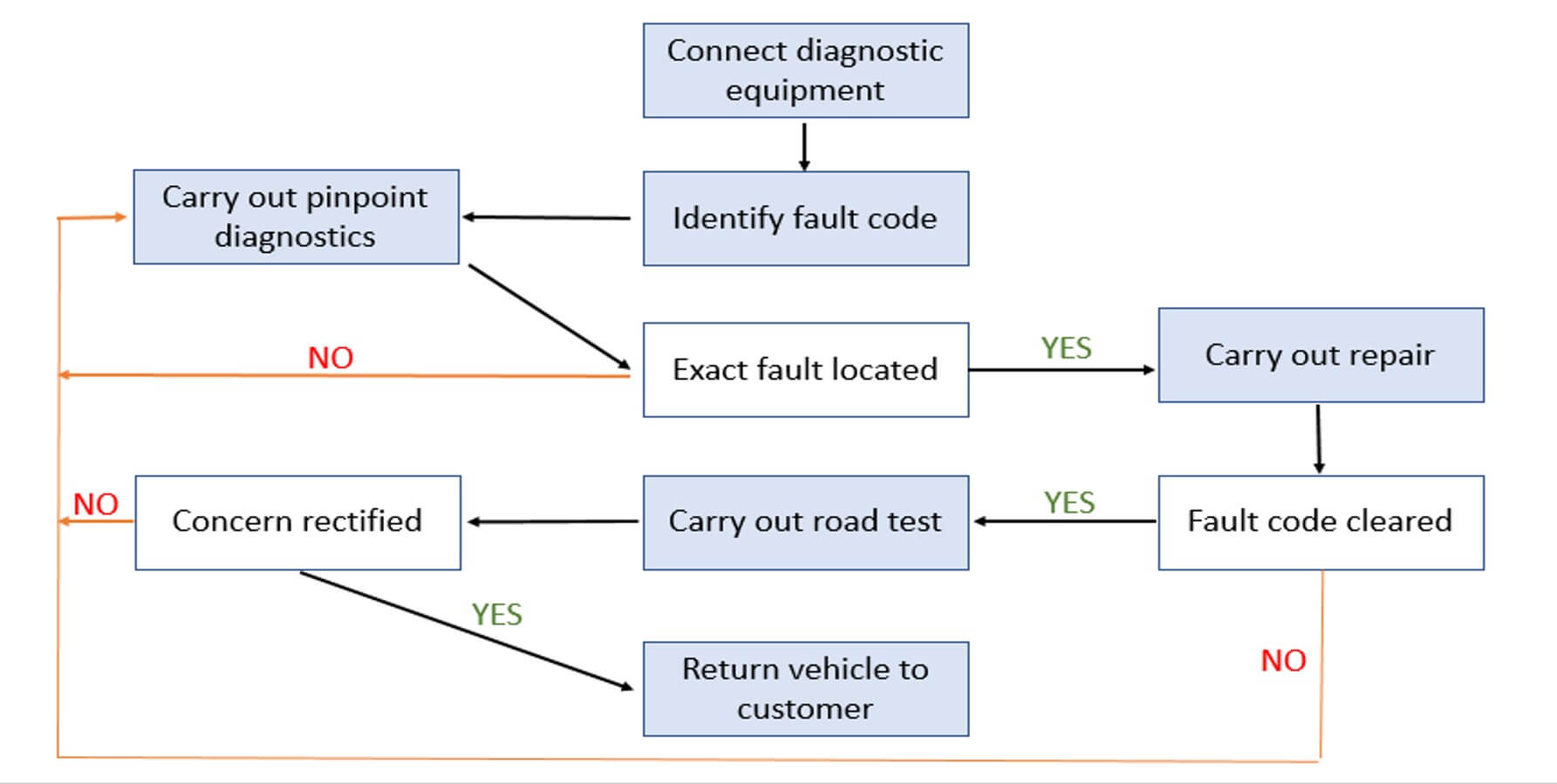
The flow chart below shows a logical approach to the use of fault codes and the additional diagnostics that may be required to efficiently diagnose faults.

Visit our Technician Library for access to Documents and Downloads
Get in touch


Find out where to buy Delphi parts